ESP 8266 with NodeMCU#
What is a NodeMCU#
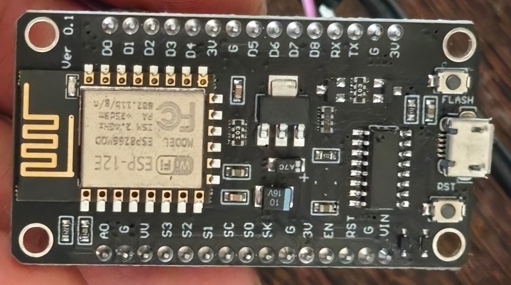
NodeMCU is an open-source development board designed specifically for the Internet of Things (IoT).
Key features of the NodeMCU#
- Integrated Wi-Fi chip ((802.11 b/g/n) operating at 2.4GHz
- SOC: Powered by a 32-bit Tensilica Xtensa LX106 CPU, usually clocked at 80 MHz (which can be overclocked to 160 MHz). For comparison, a standard Arduino Uno runs at just 16 MHz. Also comes with a flash memory of a 4 MB of storage.
- Power: MicroUSB port (for data and power) + VIN pin (4.5V to 9V).
- IO
- GPIO Pins: It features 17 General Purpose Input/Output pins, though some are reserved for internal flash communication.
- Peripheral Support: It natively supports standard communication protocols like I2C (for displays and advanced sensors), SPI (for SD cards or RFID readers), and UART (for hardware serial communication).
- PWM Support: Pulse Width Modulation is available on the digital pins, allowing users to dim LEDs or control servo motors.
- ADC (Analog-to-Digital Converter): It features one analog input pin (A0), which is perfect for reading analog components like potentiometers, light-dependent resistors (LDRs), or soil moisture sensors.
Basic setup#
Arduino IDE Setup#
- To have an initial setup first install Arduino IDE
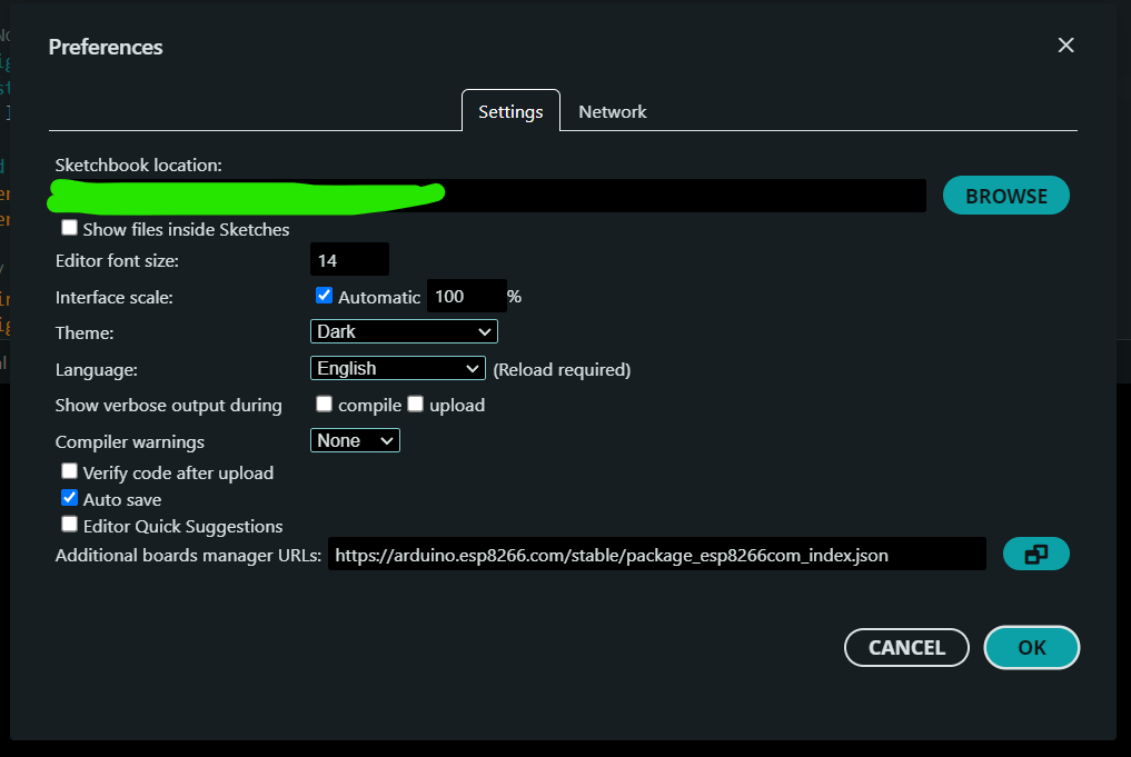
- Copy and paste this string:
https://arduino.esp8266.com/stable/package_esp8266com_index.json from esp8266/Arduino to File > Preferences > Additional boards manager URLs
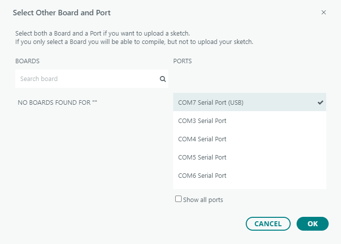
- Open Device Manager within windows and under ports check which COM port is the NodeMCU attached to. Note this down since you’ll need it later.
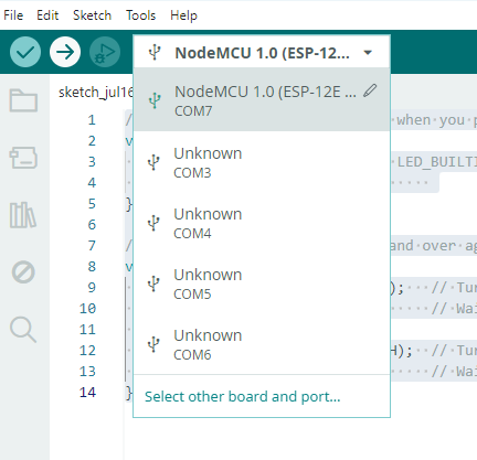
- Open the IDE once again and select the COM port you noted down. Select the COM port you noted down and select the following option
Writing your first program#
A simple blink code would look like this
 1
 2
 3
 4
 5
 6
 7
 8
 9
10
11
12
13
| void setup() {
// Initialize the digital pin LED_BUILTIN as an output.
pinMode(LED_BUILTIN, OUTPUT);
}
// The loop function runs over and over again forever
void loop() {
digitalWrite(LED_BUILTIN, LOW); // Turn the LED ON
delay(1000); // Wait for a second
digitalWrite(LED_BUILTIN, HIGH); // Turn the LED OFF
delay(1000); // Wait for a second
}
|
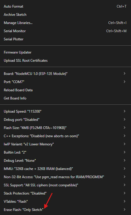
The ✅ would verify the code and ➡️ would upload the emoji to the device. Here are my settings, these could be changed from the tools dropdown. If you plan to write again then the setting of erase flash could be changed to all flash contents.
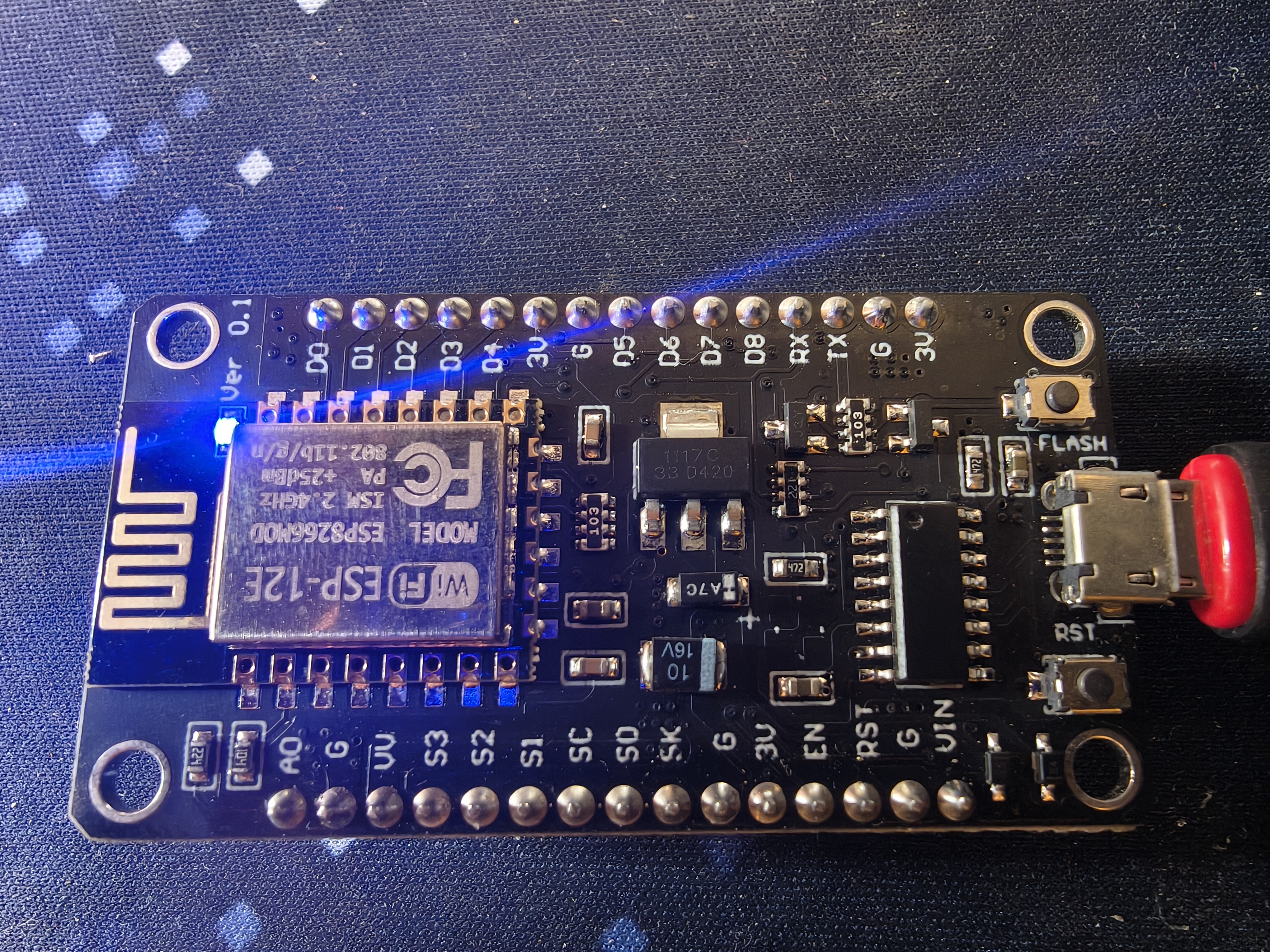
After uploading the builtin led blink would look something like this.
OTA updates with Wi-FI#
The NodeMCU does support OTA updates via Wi-Fi by default, to do this you have to copy the following script
 1
 2
 3
 4
 5
 6
 7
 8
 9
10
11
12
13
14
15
16
17
18
19
20
21
22
23
24
25
26
27
28
29
30
31
32
33
34
35
36
37
38
39
40
41
42
43
44
45
46
47
48
49
50
51
52
53
54
55
56
57
58
59
60
61
62
63
64
65
66
67
68
69
70
71
72
73
74
75
76
77
78
| #include <ESP8266WiFi.h>
#include <ESP8266mDNS.h>
#include <WiFiUdp.h>
#include <ArduinoOTA.h>
const char* ssid = ""; // insert your wifi ssid
const char* password = ""; // insert your wifi password
void setup() {
Serial.begin(115200); // baud rate must match with baud rate in tools
Serial.println("Booting...");
WiFi.mode(WIFI_STA);
WiFi.begin(ssid, password);
while (WiFi.waitForConnectResult() != WL_CONNECTED) {
Serial.println("Connection Failed! Rebooting...");
delay(5000);
ESP.restart();
}
// Port defaults to 8266
// ArduinoOTA.setPort(8266);
// Hostname defaults to esp8266-[ChipID]
ArduinoOTA.setHostname("my-nodemcu");
// No authentication by default, uncomment to set a password
// ArduinoOTA.setPassword("admin");
ArduinoOTA.onStart([]() {
String type;
if (ArduinoOTA.getCommand() == U_FS) {
type = "filesystem";
} else {
type = "sketch";
}
Serial.println("Start updating " + type);
});
ArduinoOTA.onEnd([]() {
Serial.println("\nEnd");
});
ArduinoOTA.onProgress([](unsigned int progress, unsigned int total) {
Serial.printf("Progress: %u%%\r", (progress / (total / 100)));
});
ArduinoOTA.onError([](ota_error_t error) {
Serial.printf("Error[%u]: ", error);
if (error == OTA_AUTH_ERROR) Serial.println("Auth Failed");
else if (error == OTA_BEGIN_ERROR) Serial.println("Begin Failed");
else if (error == OTA_CONNECT_ERROR) Serial.println("Connect Failed");
else if (error == OTA_RECEIVE_ERROR) Serial.println("Receive Failed");
else if (error == OTA_END_ERROR) Serial.println("End Failed");
});
ArduinoOTA.begin();
Serial.println("Ready");
Serial.print("IP address: ");
Serial.println(WiFi.localIP());
// Initialize your LED pin
pinMode(LED_BUILTIN, OUTPUT);
}
void loop() {
// CRITICAL: Keep this running so the board checks for OTA updates
ArduinoOTA.handle();
// Your blink logic goes here!
// Note: Standard delay() blocks OTA execution during the delay.
// For a basic script, this is fine, but it means the OTA check only happens between blinks.
// this section can be changed or updated to anything you wanna do with the chip
digitalWrite(LED_BUILTIN, LOW);
delay(1000);
digitalWrite(LED_BUILTIN, HIGH);
delay(1000);
}
|
and then write this to use nodemcu. After rebooting you could be seeing this option on the IDE